Hi there!
Today we will have a look on my very first pedal which I made inside ordinary aluminum box. Beside being history page this article has relatively deep explanation of the OCD overdrive circuit including very basics pedal making things as power supply, operational amplifier and other things. Also in this page you can find comparison of this pedal with original OCD. This video can be interesting to understand if component quality plays lead role.
Back in 2012 I decided to make some pretty looking overdrive. I went to youtube videos to find best sounding overdrive with simple schematic. From first video I liked very much OCD overdrive from Fulltone. The schematic is pretty common. Nothing complicated. Here I removed true bypass switch from the schematic. If you don’t know how it works you can find it very fast on many resources in internet.

This time I will try to make this article oriented more to beginners. So, If you just curios for the result go down and look to the video comparison.
Basically, this schematic can be interpreted as simple diagram.
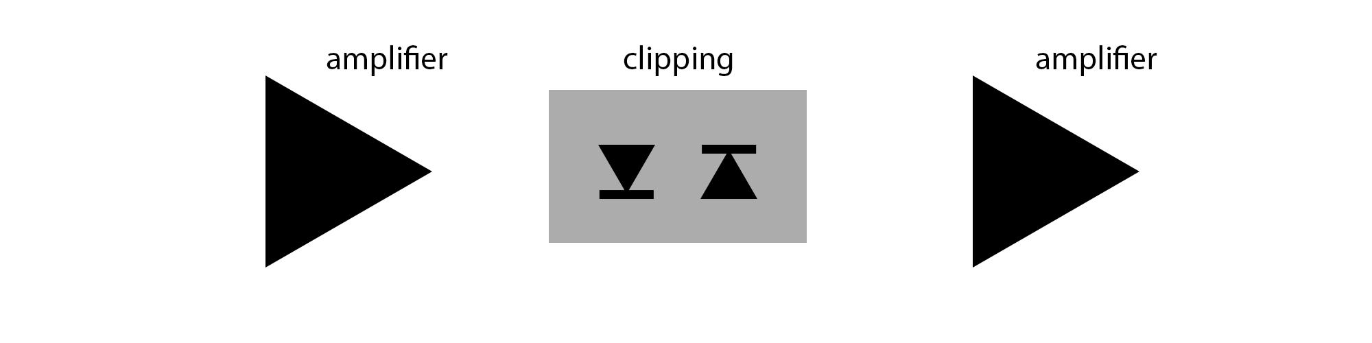
Guitar signal suffer high amplification with gain control. After this, amplified signal is clipped in the special clipping circuit based on diodes voltage drop (more in details in next parts). Then clipped signal is amplified to get initial or higher amplitude. This logic is used by many of overdrive/distortion pedals. Most of the difference is produced by eq in both amps and clipping circuit.
Lets look on the OCD schematic. Here we see that both amplifiers are made on the base of one double operational amplifier. Normally operational amplifier has double power supply with central point. But guitar pedals more often use single 9V power supply.
Power supply section:
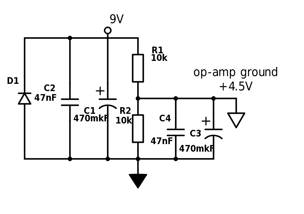
First, some very general things for most of the pedals. Capacitors C1 and C2 are here to filter power supply voltage. Our pedal will take current from this caps. C1 is the big electrolytic capacitor. Advantage of the electrolytic capacitor is that with very high capacity they are very compact. But they do not filter well high frequencies. For this reason I have installed smaller value film capacitor C2.
Diode D1 is protection diode. It is here just in case if somebody will plug power supply with wrong polarity. In this case current will not flow through pedal but will go through the diode.
To convert single power supply to double one OCD use resistor divider(R1, R2). With there help we get new virtual ground (white triangle on the picture). It works very simple. Current flows through this resistors (I=U/2R) from power source and voltage drop on each resistor is equal to half of power source (U1=U2=I*R=U/2R*R=U/2). To be honest this is not true. Beside current which go from R1 to R2 we have current which will go to our virtual ground. This mean that voltage drop will be not equal on both resistors. This effect could be reduced by decreasing value of R1 and R2. This will increase current I trough resistors and virtual ground current will be smaller comparing to it. Ground current in average should be equal to 0 as we do not have any DC voltage on the input of the op-amp. This means that we can reduce variation of voltage drop by adding capacitor parallel to R2. Here I use higher values then original to increase dynamic range of the op-amplifier.
Preamp section (gain section): Gain stage is the simplest negative feedback op-amp schematic. Lets look at all the components here.
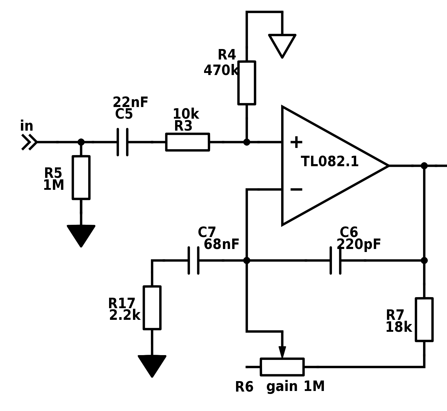
Guitar signal is coming from the left. Capacitor C5 here to remove DC signal from it. Resistor R5 links capacitor to the ground. Without this resistor when true bypass is on left connector of the capacitor C5 will fly in the air without any connection. Some voltage can arise on this side. As result you will hear “bump” sound when you will use bypass switch to turn on the pedal. With “bump” you hear how voltage on the capacitor goes to 0. Op-amp has very high input resistance. This mean that there will be more or less no current on both inputs. But as always this is not true. Because of input capacity of the op-amp some current will go to this imaginary capacitor. To reduce this current after capacitor there is resistor R3. R4 – links input to our virtual ground.
Amplification coefficient of op-amp can be calculated using simple formula for negative feedback amplifier (k=1+(R6+R7)/R17). Using this formula we can calculate maximum and minimum possible gain of this stage. Max: k=1+(1M+18k)/2.2k=464 or 53db. Pretty high, isn’t it? This means that even without diode clipping stage we will have overdrive. Lets try to imagine that in the input we have 0.5V amplitude signal from the guitar. Then in the out we will have 464*0.5=232V. With our +-4.5V power supply we are not able to get more then about +-4V output. In such extreme regime of work sound of the pedal depends on the op-amp model and power supply. By the way nothing can stop us if we want to increase voltage of power supply for this pedal. We just should be careful with maximum voltage of capacitors and op-amp itself.
Capacitor C6 is widely used with op-amps. This capacitor cuts very high frequencies which can lead to trigger self generation in oamp. C7 here playing 2 roles. First – with this capacitor we can not use virtual ground and this will decrease current through it. Second this will allow us to cut some low frequencies. Value of this capacitor varies from revision to revision.
Clipping section:

This one is probably the most interesting part in this schematic. You can ask why it has MOSFET transistors instead of diodes here? Actually what we have is diode. I will explain. Similarly to our pedal this 2n7000 transistor has its own protection diode which protects transistor from reversed polarity voltage. My first attempt to try this schematic failed because 2n7000 which I used were without protection diode. If you will take this transistor from fairchild it will works for sure. These protection diodes has voltage drop of about 0.7V. Germanium diode D2 is present not in all versions of OCD. Germanium diodes has much smaller voltage drop then silicon ones. This diode add little bit of asymmetry to the clipping. Asymmetrical clipping sounds a bit more like single ended tube amp overdrive. The resistor R8 is the very important one. With diodes it makes “nonlinear” voltage divider. First it prevent op-amp from high output current. Second it makes clipping shape more smooth.We will look on different clipping schematics in next posts.
And the last is one more amp with tone and volume control. Same with preamp here we have second part of double operational amplifier. Resistors R10 and R11 gives us amplification factor a bit smaller then 5. This mean that maximum amplitude of the signal is 0.7 times 5 (3.5).
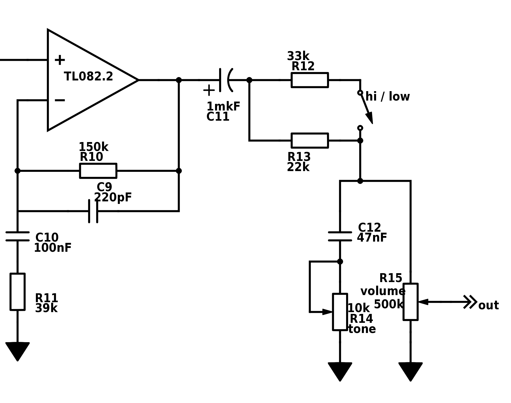
After the op-amp we have to go back to our real ground. For this reason we need coupling capacitor C11. Because pedal could be connected to devise with relatively small input impedance, value of C11 should be high. The end of the signal path is pretty similar to guitar tone and volume control. Resistors R12 and R13 together with C12 and R14 are hi frequency voltage divider. When switch is in on position total resistance of parallel R12 and R13 is smaller and and voltage drop on high frequencies is smaller which means brighter sound.
Original pedal: If you will look inside original fulltone pedal you will be surprised by very good quality components. In the video you can see last revision of OCD on this moment (end of 2016). Unlike previous revisions this one don’t have any wax or paint on the components to hide names and values. Probably they are decided that schematic is already copied million times and there is no need to hide components values anymore. Just to give you some idea about component quality: capacitor C11 is audiophile capacitor Nichicon MUSE.
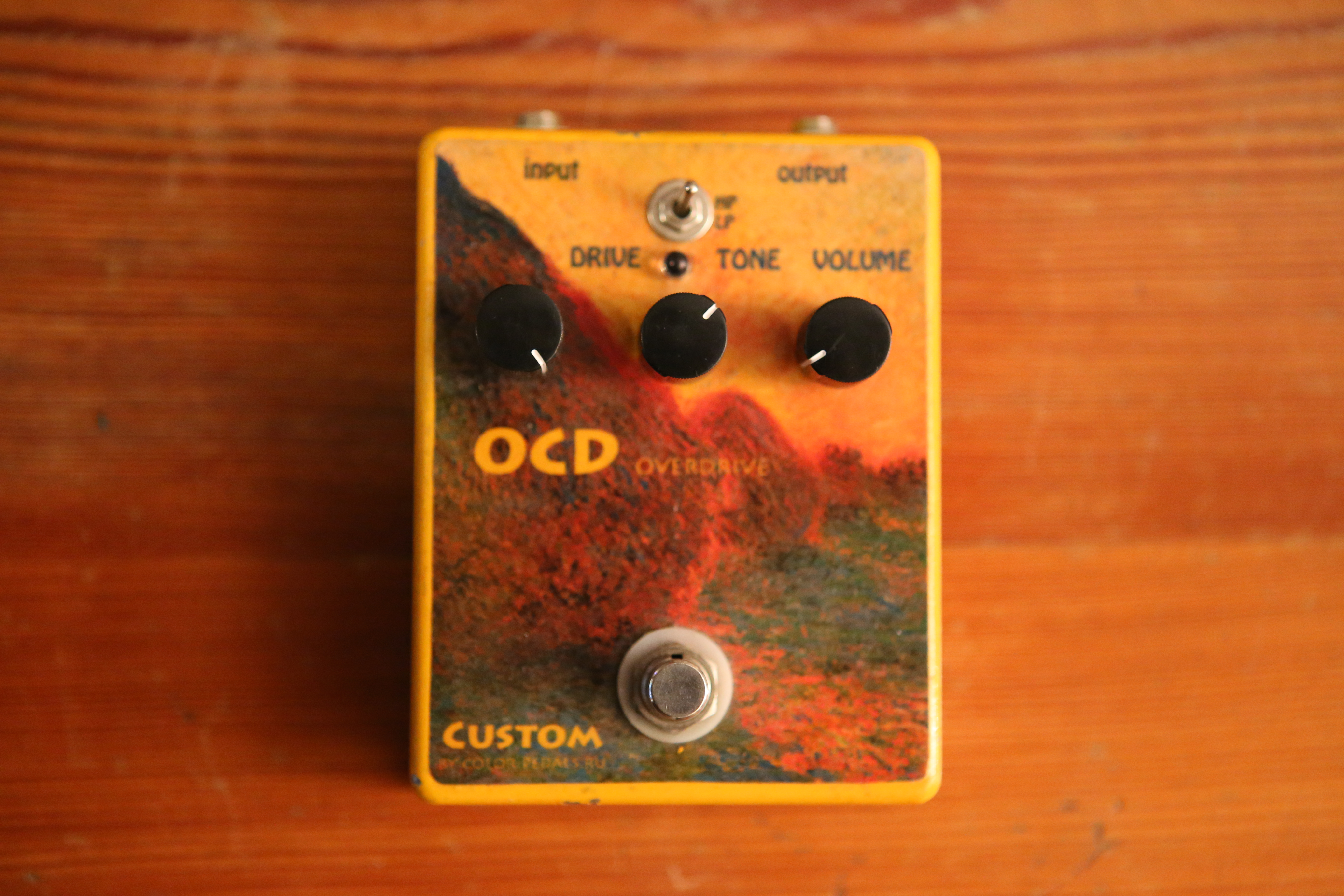
My pedal: In my pedal I was using average components. All film capacitors where made by epcos . Output electrolytic capacitor was replaced with film capacitor.
Look: I bought unfinished aluminum box. Pained it in orange color with spay with layer of spray lacquer. This finish is not very stable. If you want to make your own pedal it is better to pay a bit more and buy prepainted box. I made picture with paper sticker under layer of lacquer.
Here is the video test of my pedal beside original fulltone OCD.
If you have some questions you can ask them in comment section.
See you in coming articles. Register to stay in tune.
Really like your precise explanations. There’s lots of Efx pedal makers that could use your professional information to ensure them the viewer gets the depth of the matter. There’s not enough well versed Pedalmakers and I’m wondering if you’d be interested in being that conduit fit for them?. I’m meeting lots of creative, gifted people and helping them to be in an online publication store owned by a well established business owner that I am bringing many music equipment designers to who will have their gear imported globally from South America, Mexico, Russia, France and wherever one’s that have difficulty exporting their products due to cost and length of time sending it. Let me know if this is something you might want to consider. I can let you see the publication and speak with the owner. I’ll give you my email address and contact information and my background. Would i send it to http://www.zadviisky.com?. Thank you, Stephen Gordon I’m also on LinkedIn
Hi Stephen. Thanks for your comment and invitation. Yes you can send me the information. Currently I has some small not very commercial gear projects but I have a plan to make few original products. It will takes time because on the moment this is not my main job. You can send the information here: georgezadvitsky@yahoo.com