This small preamp was made for a fretless bass guitar that I made for a bass player from our band.
The bass guitar had 4 holes knobs and I decided to make 2 band eq preamp together with volume control and a blend knob.
Here is my schematic of the onboard preamp with 2 band Baxandall eq control.
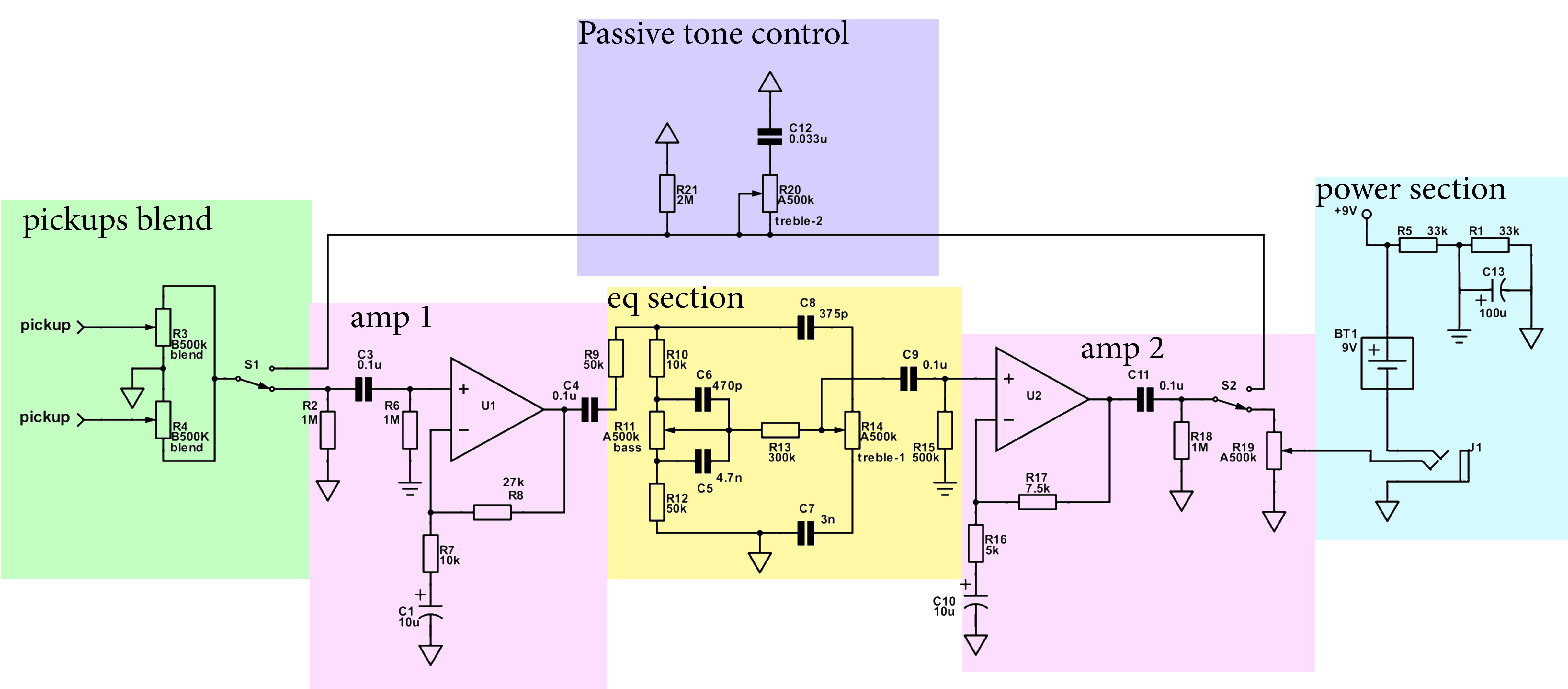
As one can see the schematic concept is very basic. After the pickups blend pot signal goes to first amplifier stage, then to eq control that attenuates certain frequencies, and to another amplifier to match guitar signal level. The preamp is powered with one 9V battery that located inside the electronics cavity.
Power
The preamp is powered by one 9V battery. If it would be possible to feet 2 batteries inside the bass electronics cavity I would go for it. Double power supply allows avoiding capacitors on the way of the signal as well as fake op-amp input grounding. Another advantage of a double power supply is increased signal headroom. Unfortunately, without additional battery cavities, it was impossible to feet 2 batteries inside the bass. To ground op-amp inputs to power supply middle point (~4.5V) simple resistor divider of 33k resistors (R1, R5) with 100uF capacitor C13 to fixate DC voltage.
To allow turning on and off preamp power supply battery ground is connected to the second channel of stereo jack plug. So if mono jack cable is plugged to the bass guitar it connects this second channel to the ground allowing current to flow through the battery and the preamp.
When a cable is plugged to the guitar preamp consumes current, no matter if the guitar is used in active or passive mode.
Amp 1
I will skip blend pot as everything is clear here. Just want to mention that this potentiometer should be special. Half zero-resistance/ half linear. However simple double linear potentiometer will work as well.
To compensate signal attenuation in the eq section (see schematic), pickups signal have to be amplified. It is always better to amplify signal right in the beginning to minimize the noise. However, there are some limitations. A maximum output voltage of first amplification stages is limited by the power supply voltage (less than +-4.5 for op-amp). Let us calculate. 0.5 volts is a quite good estimation of peak voltage which can be produced by bass (guitar) pickups. To be in a safe voltage range it is better to limit maximum voltage to 2V. This will give an amplification factor of k=4. This value defines resistor ratio R8/R7=k-1=3. The positive input of the op-amp is grounded to the middle point (4.5V) with a 1M resistor (R6). To cut DC voltage from negative input grounding through R7 we place capacitor C1.
EQ section
EQ section is nothing else as Baxandall 2 band equalizer. One can easily customize this section using free “tone stack calculator” software: http://www.duncanamps.com/tsc/
Here is a print from this program that shows possible eq range that I am using.
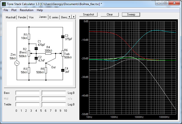
One can see that in a flat position (green line) frequency response is almost flat. It has about -20dB attenuation. This means that the signal level lowers by 10 times on this stage.
Amp 2
After eq stage signal passes to another amplification stage. Let us calculate what is the amplitude that we will have on the input of the second op-amp part. First, the signal was amplified 4 times then it was attenuated by the factor of 10. This gives us 2.5 times attenuation. If you need hotter output you can put higher gain to this stage. I stayed with 2.5.
Finally, we have master volume control before the output jack plug.
Passive tone control and push/pull switch
In order to keep full functionality of passive bass with 4 knobs, I used the same stereo potentiometer for active and passive tone control. On the schematic, I am describing a way to wire such a potentiometer with a 2-DPDT switch which is usually available as push/pull potentiometer. To keep switching silent all ends of capacitors that are connected to the switch should be grounded with resistors (R2, R18, R21).
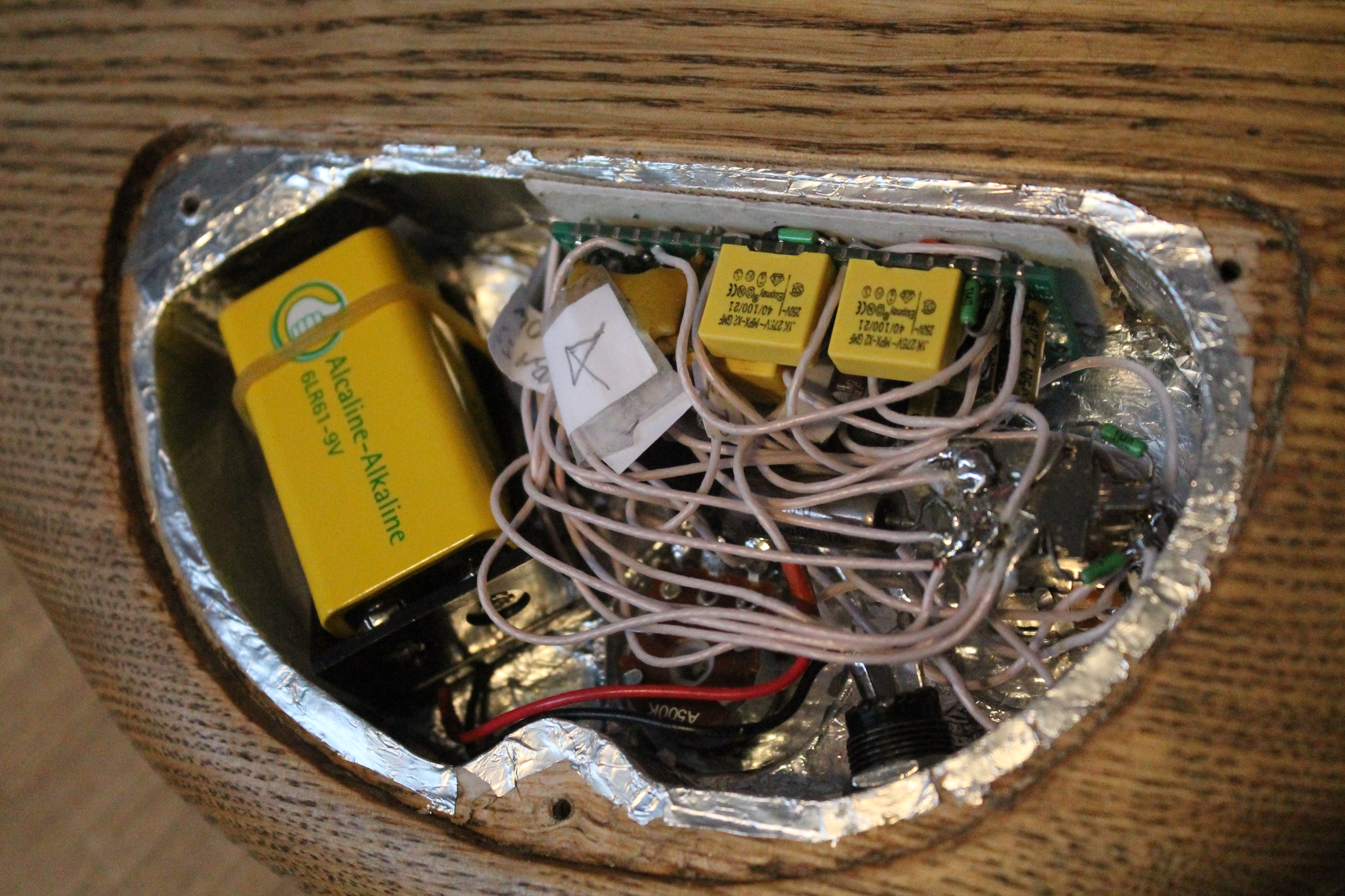
Photo
The preamp was made using simple pref-board. A component arrangement was improvised. I really like the improvisation process for small projects. Here is some photo of the bass electronic cavity with the preamp and battery holder.
Video
Leave a comment if you have some questions. And if this page helped you to make your preamp send me photo/video.